Cyberdeck Part 4
In Cyberdeck Part 3, I redesigned the screen brackets, and printed up panels for the USB hub and 12V power switch/connector as well as brackets for the G90 control head. I also printed up a center panel with speaker holes and a window for an OLED display.
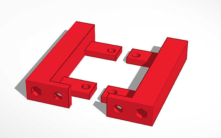
In this update, I designed some brackets to hold the G90 main chassis in place. Here’s the rendering from TinkerCAD of the G90 brackets:
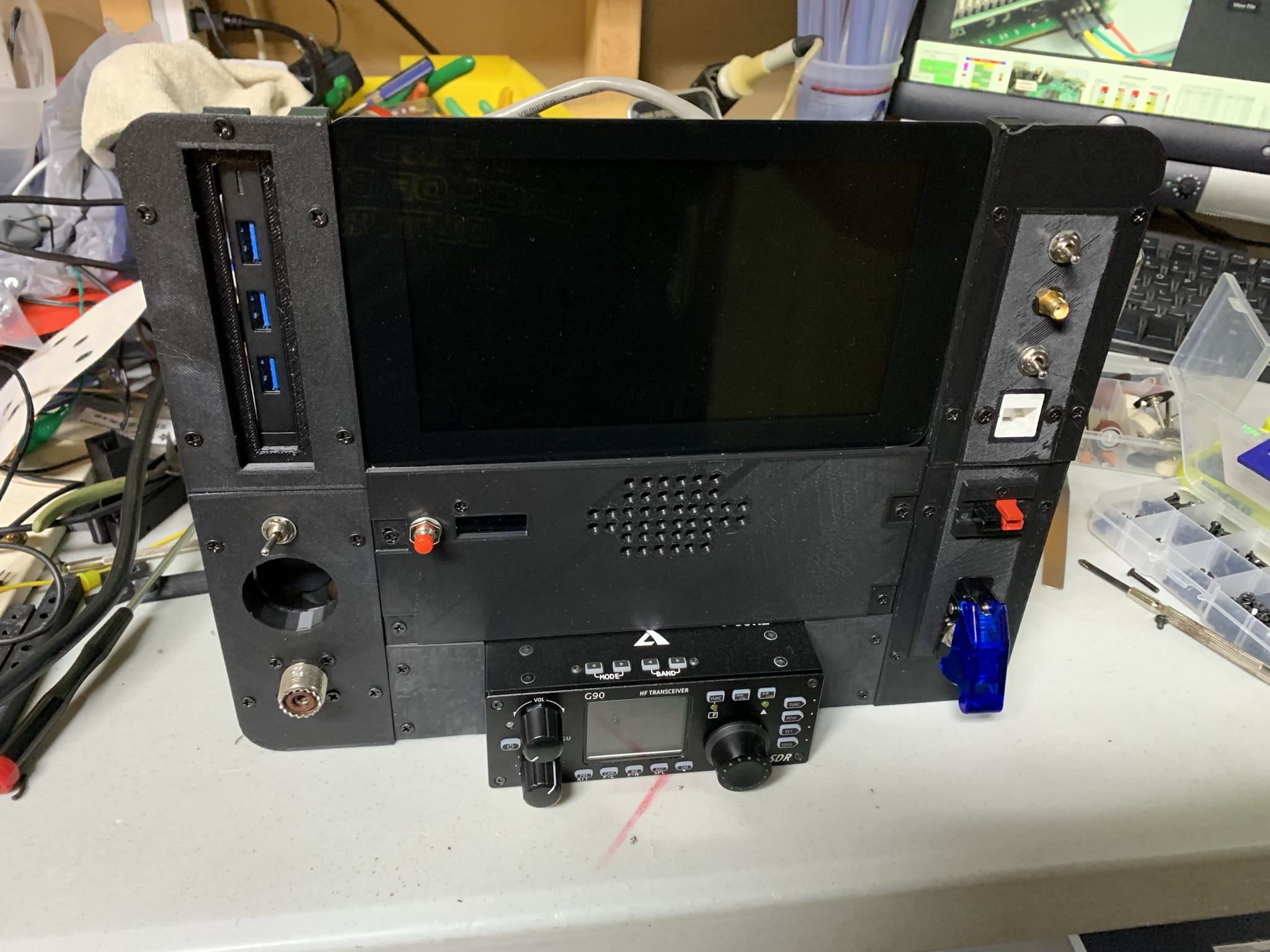
I added a panel with two switches, an SMA connector, and a RJ45. In the future, I’d like to add my DMR hotspot to the Cyberdeck. One of the switches will be for turning the DMR hotspot on/off, while the SMA panel connector will bring the DMR antenna out. The RJ45 has been wired up to a short ethernet cable that plugs into the Raspberry Pi. For the second switch, I’d like to wire it to a GPIO on the Pi and have it switch the Pi between hotspot mode and client WIFI mode.
The next panel I added has a SO-239 panel connector to bring the antenna connection out from the G90. On the inside I’ve soldered a piece of coax with a PL-259 on it that connects to the G90. This panel also has a port for a cooling fan, and a switch to power the fan on/off.
I found an existing design on Thingiverse for a PowerPole panel mount bracket. I’ve printed up this design and added it to the power panel. It’s wired up to the main power switch and then to a screw terminal distribution block. Here’s where the G90 power leads are connected, and a couple of DC buck converters connect here too. The buck converters supply 5VDC to the Pi, and the USB hub. Here’s a shot of the assembled panel out of the case.
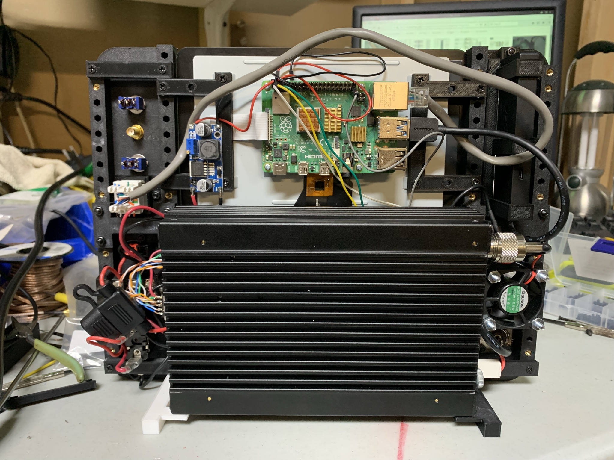
Here’s the backside with some of the components mounted and wired up:
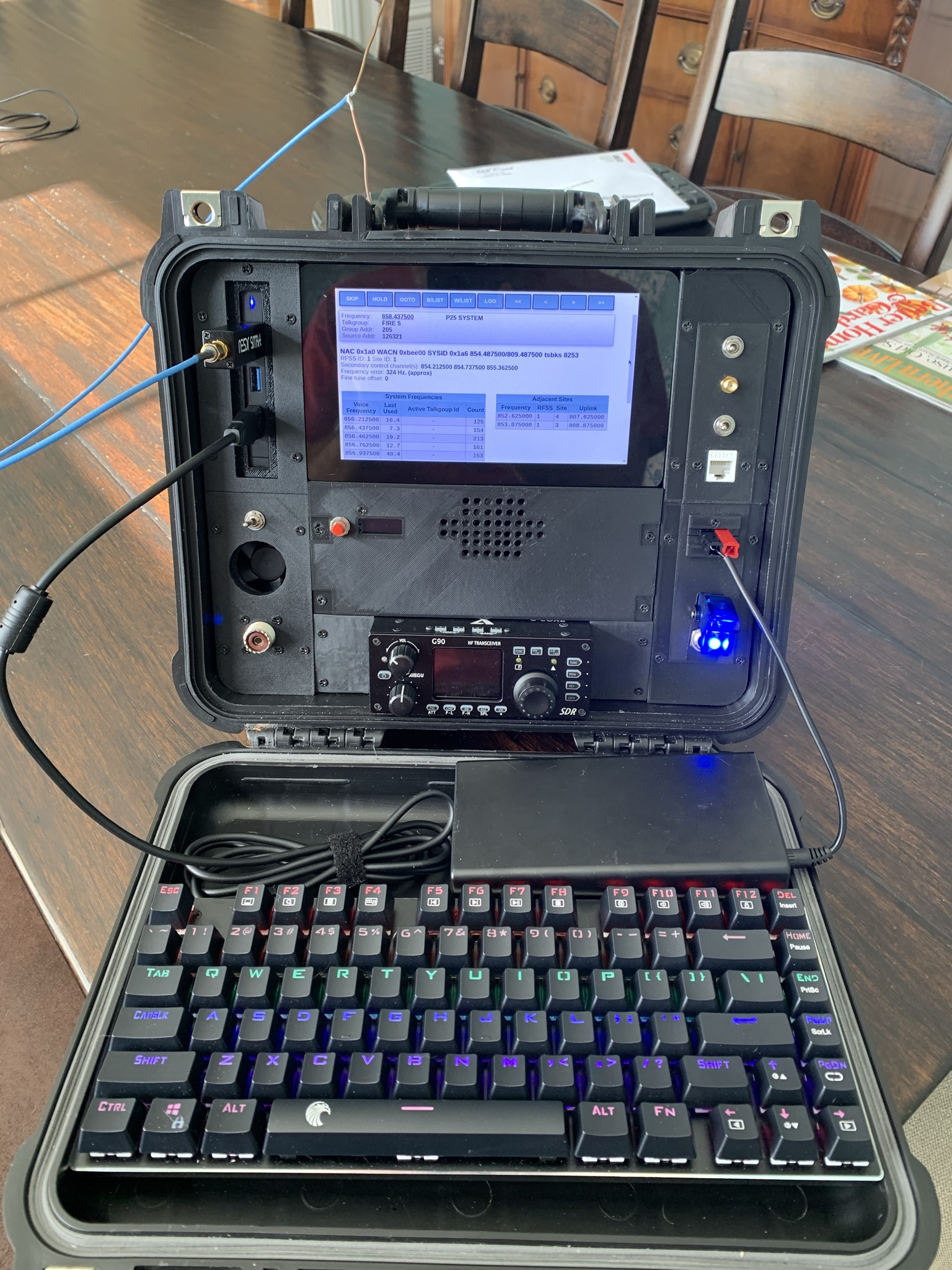
Here we are assembled in the case, powered with a battery.
 In the picture I have a
Nooelec
NESDR
SDR plugged into the USB hub and a P25 Trunk Tracker running on the Pi to
receive my local public safety radio system. Check out that quick and dirty
800mhz dipole stuck on the top! It’s some copper wire cut to 1/4 wavelength at
800mhz and soldered to a SMA pigtail I had laying around. It works remarkably
well when it’s near a window of my house.
In the picture I have a
Nooelec
NESDR
SDR plugged into the USB hub and a P25 Trunk Tracker running on the Pi to
receive my local public safety radio system. Check out that quick and dirty
800mhz dipole stuck on the top! It’s some copper wire cut to 1/4 wavelength at
800mhz and soldered to a SMA pigtail I had laying around. It works remarkably
well when it’s near a window of my house.
In the next update I’ll be adding the audio interface from the Pi to the G90 for digital HF modes, and hopefully by then I can get a video posted of the deck in operation on the HF bands!
Until then, Happy Hacking!